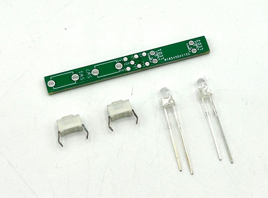
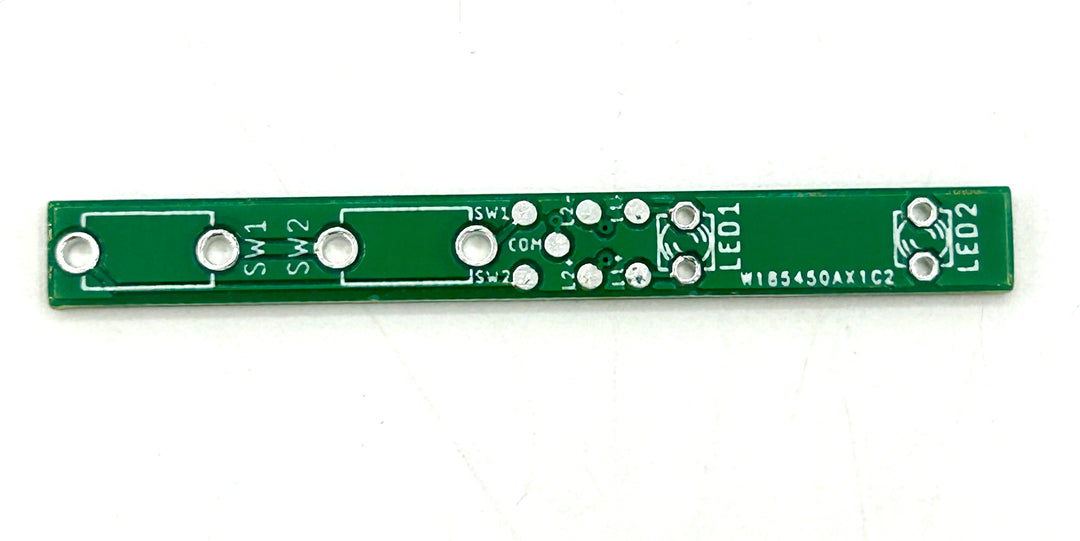
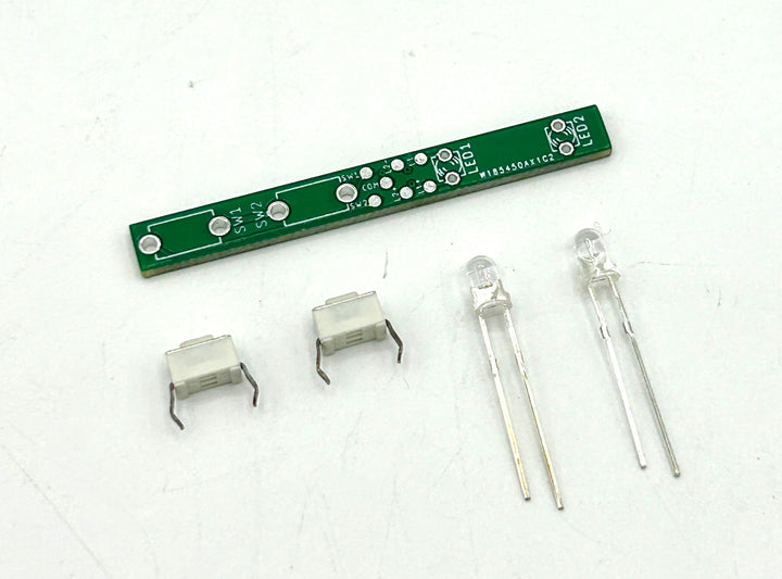
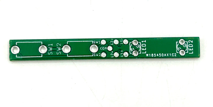
Helper board PCB design for the Creepy Uncle control box. This is a custom circuit made to make the control wiring much easier for the tactile switches and accent LED's.
This will fit the specific 3D printed board holder for the control box that is included with the chassis design, but you can also add the holder as an individual item with the helper board.
Pad layout:
-SW1 pad for the first tactile switch
-SW2 pad for the second tactile switch
-COM common ground wire for both tactile switches
-L1+ positive wire for accent LED1
-L1- negative wire for accent LED1
-L2+ positive wire for accent LED2
-L2- negative wire for accent LED2
For installation, push the tactile switches and and accent LED's in the proper through hole soldering spots. Add your solder from the backside of the helper board. You can cut off any excessive length of the the legs if necessary.
Use as small of wire gauge as possible, 30-32AWG is recommended.
Please use caution when soldering as solder pads are delicate and can come off with too much heat.


